O-band optical amplifier for monitoring 100G Ethernet
Summary
This article shows an application of O-band optical fiber amplifier (PDFA) for enhancing monitoring capability of 100G Ethernet. It is shown that a PDFA allows for delayless and multiple replications of 100GBASE-LR4 signal for connecting multiple network monitoring appliances, by compensating the branching loss of an optical TAP (Test Access Point) and 1xN splitter.
Network monitoring using optical TAP
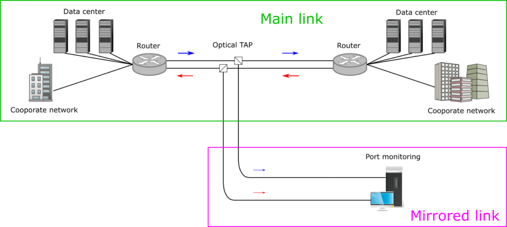
Network monitoring is an essential task for a network operator. There are many schemes for network monitoring, and the use of an optical TAP (see Figure 1) is a preferred choice for high reliability and minimum service downtime. An optical TAP is a passive optical power splitter which possesses a very low failure rate; therefore the risk of failure is minimized. In addition, maintenance or failure in the mirrored link does not affect the service in the main link. The 100G Ethernet uses the O-band for optical transceivers, and thus Eribum-Doped Fiber Amplifier (EDFA) cannot be used. Instead, PDFA – which is much less known compared to EDFA – can be used in the 1310-nm wavelength range. In the following, we experimentally show that our PDFA (AMP-FL5611-OP15) can be used for connecting at least eight monitoring appliances in the mirrored link.
Validation of feasibility
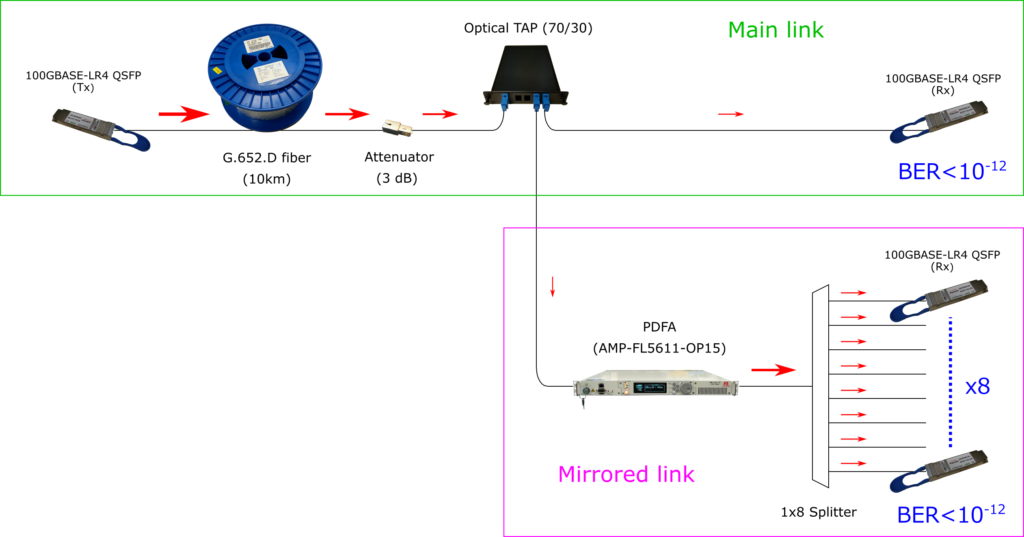
Our experimental setup is shown in Figure 3. The setup emulates: (1) the main link for actual data transmission, and (2) mirrored link for network monitoring. The main link had the following three components: 10-km-length G.652.D fiber spool, 3-dB attenuator (emulating splice losses), and 70/30 TAP. The total attenuation of these three components was about 9 dB at 1310 nm. The mirrored link was separated from the main link by the 70/30 TAP, and the TAP was followed by these two extra components: PDFA (AMP-FL5611-OP15), and 1×8 optical splitter. These two components allows for re-boosting the signal and providing sufficient optical power to eight monitoring ports, such that each of the eight signals can be read by a standard 100GBASE-LR4 receiver. The validation of this configuration was done by conducting a series of BER measurements for all the nine receiver ports (one main link and eight output ports from the splitter). The BER measurements were conducted using a 100GBASE-LR4 transciever (Gigalight GQS-SPO101-LR4C) and a QSFP optics checker (Gigalight 40G QSFP+ & 100G QSFP28 Optics Checker). The measured BERs were <10-12 for all the nine ports. In order to confirm that the system operates with margin, we added a 1-dB attenuator in the main link (before the TAP) and in the monitoring port (after the splitter); the BERs were still <10-12 for all the nine ports, showing that this configuration possesses a sufficient amount of margin.
Advantages
The most important feature of this scheme is that the packet replication is done in the optical domain and thus does not include any O/E-to-E/O conversion. This feature leads to the following two important advantages: Essentially delayless (Typ. 100~200 ns, for light travelling in the amplifier), and Bit-rate insensitive. The delayless replication may be of a huge benefit where signal delay needs to be minimized (e.g. financial trading). The second feature would secure potential future upgrade when 200G/400G-LR4 emerges in the market.